Designing a wireless gesture recognition glove, part 3
September 24, 2013
This is the third part of the wireless glove series. Part one is here and part two is here. Today I’ll talk about PCB layout.
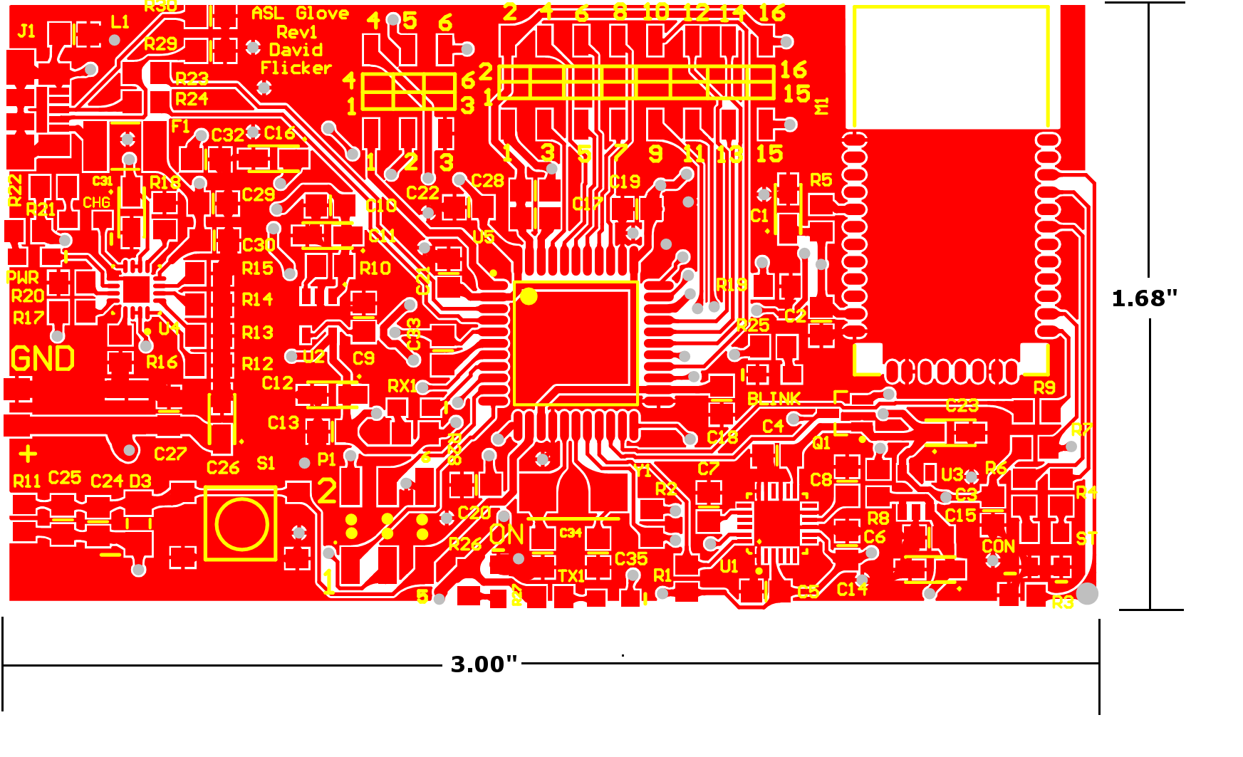
Here is what the Rev1 board top layout looks like:
Board Size and Design Constraints
I really wanted the complete board and battery to fit on the back of the hand for ergonomics and easy of connection to various sensors on the fingers and palm. In addition, I could keep all the components on the same board as the motion sensor needed to be on the hand anyway. Measuring my hand, I had an approximately 3.2" x 1.75" area to work with. I chose a rectangular board design to maximize the area I had to work with. However, Rev2 should use a rounded rectangle board as it still provides plenty of board area to work with but lacks sharp corners that are undesirable on the back of someone’s hand.
Passive and Misc. Component Selection
I used 0805-sized parts wherever I could because then I have less footprints to manage and they are just big enough to hand solder easily. All the ceramic capacitors, resistors, and the ferrite bead are 0805. The tantalum bulk capacitors are a slightly larger 1206. All the parts are surface mount so that the bottom of the board is flat and so the lithium battery can easily be placed underneath.
Layout
I started by placing the major components on separate areas of the board and organizing a flow from left-to-right. Power and USB come in from the left, go into the microcontroller in the middle and connect to the motion sensor and Bluetooth module on the right. I then routed the USB data lines through their terminating resistors and into the microcontroller so that I shouldn’t have to worry about signal integrity or noise issues on the high-speed USB lines. Next, I added the components that need to be close to one of the major components such as bypass capacitors and the crystal. I then added the rest of the parts, which sounds trite, but I find layout to be a holistic process so I often need to jiggle all the parts a few times to get everything to route and fit where I want it to. Finally, I add a ground plane on the front and two power planes (one 5V and one 3V3) both for aesthetics and cargo-culting ground planes even though this board shouldn’t require one.
On-Board Documentation
For a prototyping board especially, the board should be as descriptive as possible by itself without the original layout or board documentation. Therefore, I tried to label everything as clearly and usefully as possible. Every LED on the board is labeled with what it indicates. All the inputs and output pin numbers are labeled and the battery connection polarity is noted. I added the boxes and dots to the middle of the headers to make it clear whether it’s a male or female header. Every part also has its descriptor nearby (CXX, RXX, etc.). I’m not yet sure if keeping the descriptors is a net positive. It’s somewhat useful for assembly but during assembly, I have access to the full layout and I usually want to check which part I’m putting down anyway. They make it harder to actually layout the board as I don’t use tented vias and I can’t place designators over other parts’ pads increasing the size of the board. Finally, I add the board’s name, its revision number, and my name for identification.
Final Sanity Check
From someone’s blog, I learned a really good tip for sanity checking board designs before sending them out for the slow and somewhat expensive process of manufacturing. I print out the draft layout at 1:1 scale and first make sure the board shape and size matches where it is supposed to go. On this board, after I did this step, I realized that I had misremember the size of my hand and needed to shrink the board by one inch. Then, place each physical part in turn on the paper board and make sure it matches the expected footprint. I could have fixed the first revision of the first two boards I designed if I had checked all the footprints with physical parts before having them made.
Finally, I export the gerbers and send them off to the fab.
Final Renders (OSH Park)

